Multilevel Car Parking Ventilation System
When cars enter, exit and drive through your enclosed parking garage, they release toxic and non-toxic gases. If car engines were perfect, the vehicles would release carbon dioxide (CO2), water (H20) and Nitrogen (N). Unfortunately, car engines are not perfect, and they carbon),NOxoxides (various nitrogen typically release unburned fuel and fuel particles, ),O2) and water (H2(CO), carbon dioxide (COmonoxide So Ventilation of car parks is important and also to clear smoke in the event of a fire There are broadly two methods of complying with the Building Regulations regarding ventilation and these are by natural or mechanical ventilation Natural Ventilation This is the preferred method of ventilating car parks and simply requires openings to fresh air being provided to equal a percentage of the floor area of the car park Mechanical Extract The rules for mechanical extract state that for control of fumes a system which is capable of limiting the concentration of CO within the car park to below 30 parts per million averaged over an eight hour period should be provided. For smoke clearance 10 air changes per hour should be extracted.
Traditional Systems (Ducted mechanical extract systems) Traditional mechanical extract systems use sheet metal ductwork to transport the fumes or smoke being extracted to the external atmosphere. The ducts must be evenly distributed around the car park and also drop to low level to provide the low level extract points. The system should be capable of operating at temperatures of up to 300°C for 60 minutes, and ductwork and fixings should be made from materials that have a melting point above 800°C.
Ducted mechanical extract systems are permitted by regulations but are rarely used nowadays • The ductwork runs underneath the ceiling, reducing the already restricted height normally available. • Down stand beams require the ducting to be set down below them, thus diminishing the height even further. • Low level extract points are required, often needing protective barriers to surround them, and these take up valuable floor space. • High initial and running cost for maintenance
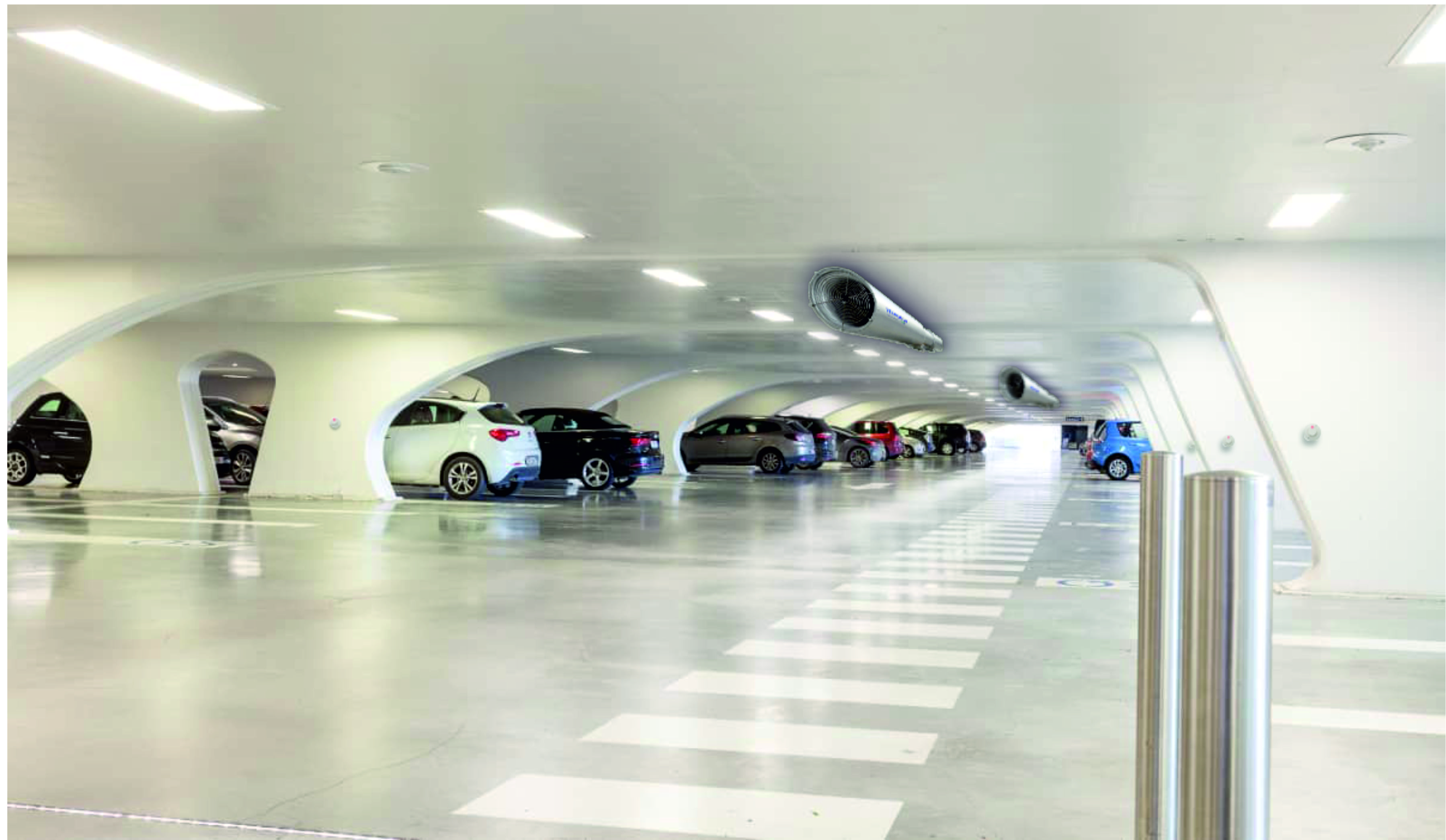
- DUCTLESS SYSTEM : Jet fan, jet thrust, jet vent, impulse or induction systems All the above are different names for the same basic system and have become increasingly popular as they can overcome many of the problems associated with sheet metal ductwork. Jet fans were developed for ventilating tunnels a small jet of air at extremely high velocity which causes surrounding air to be entrained and in a confined space like a tunnel or car park can be used to move a large volume of gas. Impulse ventilation systems push the air through the car park towards a single extract point, rather than pulling it to multiple extract points as a ducted mechanical extract system would.
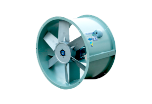
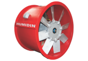
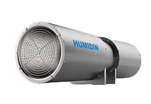
The number and location of fans are carefully chosen to match the system design requirements and to ensure that there are no dead spots (where there is no airflow) for fumes and smoke to stagnate and collect. In addition to the space saving as well as dead spots are prevented jet fan systems have other advantages over traditional ducted systems. Energy saving Jet fan systems are often combined with CO detection to initiate them for CO control and these can ensure that fans are precisely controlled to dilute pollution without fans running unnecessarily with large potential energy savings. Low noise Because the main extract fans are relatively smaller and for CO control run at lower speeds than a traditional system the noise generated is considerably lower. Low cost Jet fan systems cost less than a comparable ducted system. - JET FANS : The jet fans are positioned to ensure that fumes and smoke are transported quickly and efficiently to the main extract points. Jet fans can provide up to 50N of thrust, Suitable for most small to medium sized car parks, induction fans can provide up to 100N of thrust, Suitable for medium to large car parks. Jet fans are flexible and can be adapted to suit changes in the use of space. The transferred volume of air being several times greater than the actual flow volume of the fan. Velocity profile of Jet Fan Technology and material JET Fans are available in many versions according to its sizes. (THREE fan sizes, 315mm , 355 MM and 400mm diameter ). The casing for all of these products is made of galvanised sheet steel and noise suppressors integrated on both sides. The impeller wheel usually is made of pressure die-cast Aluminium The centrifugal impeller is made of sheet steel, welded and coated.
Operation of Jet Fan : The Jet fan can be used for partial smoke extraction , ventilation or even in case of Fire. In normal day-to-day operation, the Jet fans are controlled by the CO system – in accordance with the concentration threshold setting. In this way, carbon monoxide- contaminated air is extracted from the car park. This takes place with either just a few Jet fans operating at a low speed, or with all system components operating at a higher output level, depending on the concentration in the air. The recommendation are that the system should provide 6 air changes per hour (ACH) for day-to-day ventilation on all levels and 10 ACH on the fire floor in the event of a fire.
Smoke extraction – the Jet fan smoke extraction system In the event of smoke needing to be extracted, the Jet fans are immediately activated at maximum speed by smoke detectors, regardless of the CO system setting, in order to extract smoke from the area of the fire. The central ventilation shafts are switched to full power at the same time. A significant advantage of the Jet fan smoke extraction system lies in the fact that smoke can be partially extracted from the immediate area of the fire. In other words, the Jet fans can be used to control smoke levels as well. This avoids the costly process of dividing a car park up into separate sections to reduce the spread of fire. - Examples of Fans for induction systems : Jet thrust fan, jet fan, jet vent fan or impulse fan: An axial flow fan mounted within an inlet and outlet cylindrical silencer. jet fans can provide up to 50N of thrust. Suitable for most small to medium sized car parks. Induction fan: A centrifugal fan with an air inlet positioned beneath the body of the fan and discharging through a reduced size opening, induction fans can provide up to 100N of thrust. Suitable for medium to large car parks,
- TECHNICAL SPECIFICATION :
- A control system : Description designed to efficiently manage the car park ventilation equipment. It helps maintain good air quality when the car park traffic is high and conserve energy when it is low, controlling operation of the fans according to the conditions in the space to save energy and will usually incorporate CO sensors and fans speed control.
- Installation of JetFans : Ceiling features To make the system more effective, position JetVent Fans in-line with supporting ceiling beams as illustrated in Figure 7(a). If this is not possible, the system becomes less effective and more fans may be needed.
Vertical clearance Sufficient vertical clearance ensures maximum flexibility in system design. JetVent Fans may be recessed between ceiling beams to minimise the height of the system. - Obstructions : If there is no option and the JetVent Fans must blow across ceiling beams, have to be positioned a sufficient distance away from the obstruction as illustrated A horizontal distance eight times (8x) the height of the obstruction is generally sufficient. Nozzles on the JetVent units are specially designed and angled downwards for this purpose. Clashes with other services Pla0ce mechanical service components, such as sprinklers, signs and pipework out of the JetVent’s discharge pattern area.
Fans placed in series As shown at table below ,the maximum and recommended spacings between JetVent Fans for different levels of fan thrust. These spacing distances are guidelines for fans placed in series. When using these spacings. Analysis will determine whether this is achieved in a particular car park design. In some ideal cases, designs using the maximum distances have been effective. - Computational fluid dynamics (CFD) : CFD can provide detailed prediction of air movement, temperature and smoke density throughout the car park, taking into account the often complex geometry of individual buildings, This level of detail cannot be provided by any other means. A Computational Fluid Dynamics (CFD) analysis is often required to prove and further refine the design as Fans may need to be re-orientated, or in some cases, added or removed. The image shows the velocity vectors produced by the CFD representation of a Colt Cyclone 100 fan unit.
HUMIDIN © 2023. All rights reserved.